Saved Bookmarks
| 1. |
A sinusoidally alternating emf is applied to an LCR series circuit . (i) Define the impedance of thecircuit . (ii) Obtain theexpressions for the impedance and the phase difference between theemf andcurrent from the phasor diagram. (iii) Discuss thebehaviour of thecircuit for different relative values of thetwo reactances in thecircuit. |
Answer» Solution :Suppose a sinusoidally alternating emf E, of peak value `E_(o)` and frequency f , is APPLIED to a circuit containing a pure inductor ( inductance L), a RESISTOR ( resistance R) anda capacitor (capacitance C), all in series, Fig (a). 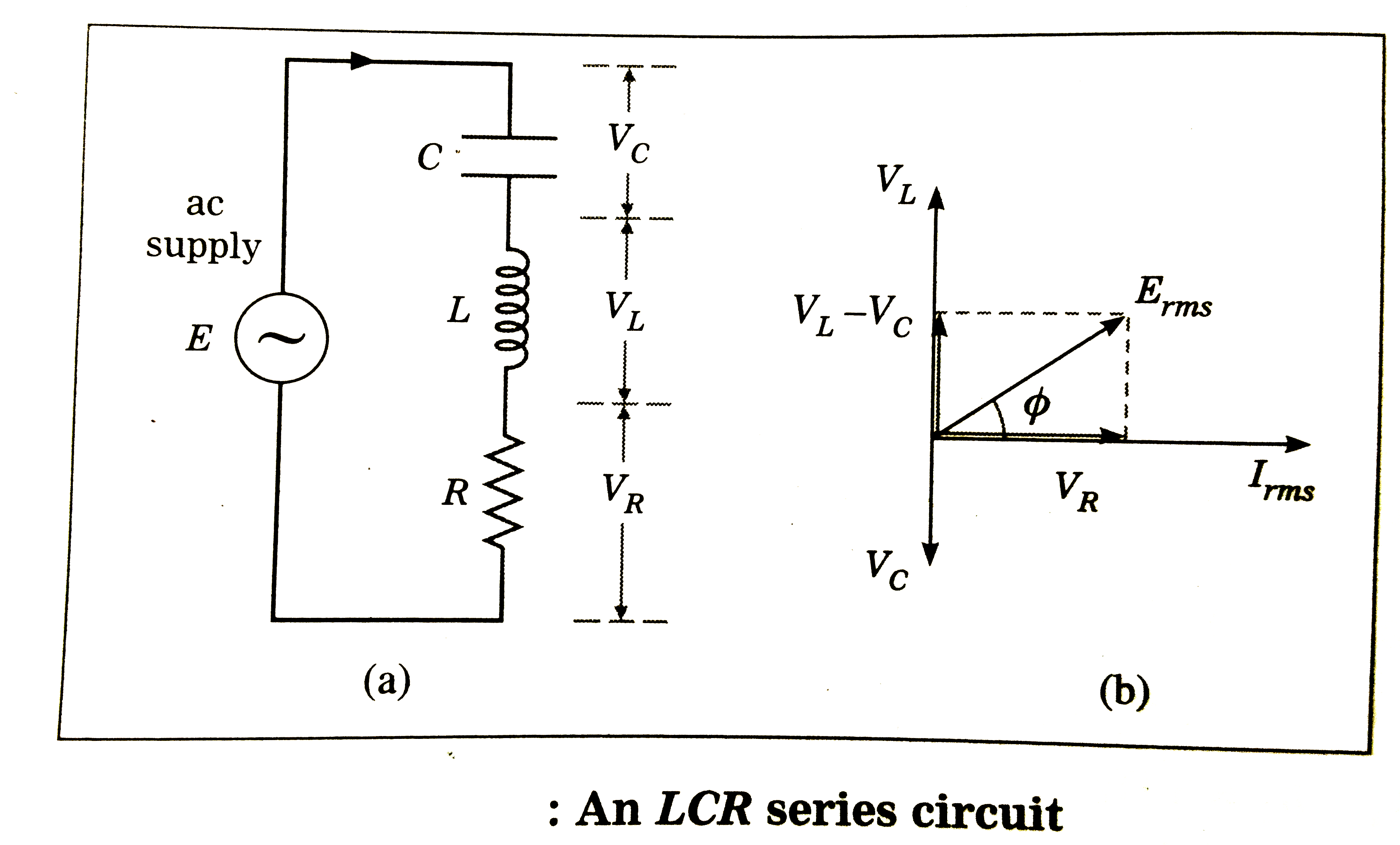 (i) The impedance Z of the circuit is defined as theeffective resistance offfered to analternating current and is given by` Z = V_(rms) //I_(rms)` . (ii) Let the current at any instant be`I = I_(o) sinomega t`, where `I_(o)= E_(o)//Z -=` the peak current and ` omega = 2 pi f`. Thep.d. `V_(R)` across theresistor is in phase withI and isgiven by `V_(R) = I R`. Thep.d. `V_(L)` acrose the inductor leads `90^(@)` on I, and `V_(L(rms)) = omega L I _(rms)= X_(L) I_(rms)`, where ` X_(L) = omega L` = the INDUCTIVE reactance . The p.d. `V_(C)` across the capacitor LAGS ` 90^(@)` on I, and`V_(C(rms))=(I_(rms))/(omegaC) = X_(C) I_(rms)`,where `X_(C) = 1//omegaC` =the capacitive reactance. Since the current is thesame for all the circuit elements, this is thefirst phasor drawn in thephasor diagram, Fig. (b) . Other phasors representing the instantaneous values of the sinusoidally alternating quantities arethen drawn in relation to this. In can be seen in thephasor diagram, that the p.d.s `V_(L) and V_(C)` are in antiphase so that the magnitude `E_(rms)` of thevector sum of all three p.d.s is `E_(rms) = sqrt(V_(R)^(2) +(V_(L) -V_(C))^(2))` ` = I_(rms) sqrt(R^(2) +(X_(L)-C_(C))^(2))` Hence, theimpedance of thecircuit is ` Z = sqrt(R^(2) +(X_(L)-X_(C))^(2))` ` = sqrt(R^(2)+(omegaL - 1/(omegaC))^(2))` The phase difference `phi` between the emf and current is given by ` tan phi = (V_(L) -V_(C))/V_(R) =(X_(L)-X_(C))/R = (omegaL - (1//omegaC))/R` (iii) If `X_(L) gt X_(C)`,the circuit behaves inductively and the current legs onp.d. For `X_(L) lt X_(C)`, the circuit behaves capacitively and the current leads on p.d. (`phi` negative). For ` X_(L) = X_(C), phi = 0`, the current and emf arein phase, and the circuit is purely resistive. |
|