Saved Bookmarks
| 1. |
Analyse the circuit shown in the figure in steady state |
|
Answer» Solution :`8i_(1)+13i_(1)+1(i_(1)+i_(2))-24=0` `22i_(1)+i_(2)=24`ldots (1) For RIGHT mesh,`5I_(2) +2i_(2) + 1 + i_(2) + 2i_(2) - 13I_(1)-8i_(1) = 0` or `10I_(2) - 2i_(1) + 1 = 0ldots(2)` From equations (1) and (2) `i_(1) = 1 amp` and, `i_(2) = 2 amp` Now, CONSIDERING current in different parts when capacitors were charging (e. when Lwwwisti 20 steady state was not reached) Current charging 2 muf CAPACITOR= current charging 1 muF capacitor + current charging 3 muF capacitor If steady state charges on 1 muF and 3 muF capacitors are a `q_(1)muC` and `q_(2)` `muC` respectively, then charge on` 2 muF` capacitor wil be`q_(1)+q_(2)` Hence, in steady state the circuit will be as shown in the figure . Applying Kirchoff.s voltage law on mesh BCKJB `5i_(2)+q_(2)/(3)-q_(1)/(1)-8i_(1)=0` `ldots(3) 512 +9 9 -81, = 0(3)` For mesh JKFGJ`q_(1)+(q_(2))/(3)-q_(1)/(1)-8i=0ldots(4)` In equations (3) and (4), substituting. `1_(1) = 1 amp. i_(2) = 2 amp` `q_(1)=4muC` `q_(2)=6muC` 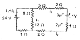 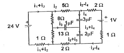 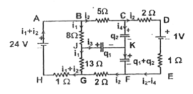
|
|