Saved Bookmarks
| 1. |
Draw the circuit diagram of a full wave rectifier. Explain its working showing its input and output waveforms. |
Answer» Solution :The circuit arrangement of a full-wave rectifier using two diodes `D_(1)`, and `D_(2)`, has been drawn here. We use a centre tap transformer having its SECONDARY wound into two equal parts such that voltages at any instant at A (input of DIODE `D_(1)`,) and B (input of diode `D_(2)`,) are out of phase with each other. Let initially input voltage at A is positive then it will be negative voltage at B at that instant. Consequently diode `D_(1)`, being in forward bias, conducts while `D_(2)`, being in REVERSE bias, does not conduct. We get output current and hence output voltage across load resistance R, joined between X and Y due to `D_(1)`. Aler hall-cycle of a.c. input, voltage at A becomes negalive and that at B positive. Now diode `D_(1)` does not conduct but `D_(2)` conducts and output voltage is again OBTAINED across `R_(L)` in the same direction. Thus, output is obtained throughout the input wave cycle. The input and output waveforms have been shown in the figure. 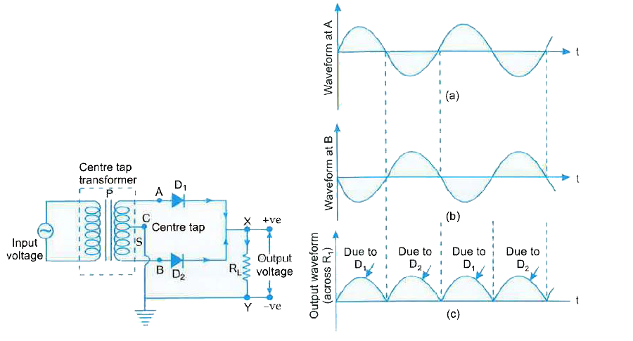
|
|