Saved Bookmarks
| 1. |
In the circuit given in the figure, both batteries are ideal . Emf E_1 of battery 1 has a fixed value, but emf E_2 of battery 2 can be varied between 1.0V and 10.0 V . The graph gives the currents through the two batteriesas a function of E_2 but are not marked as which plot corresponds to which battery. But for both plots, current is assumed to be negative when the direction of the current through the battery is opposite to the direction of that battery's emf (direction of emf is from negative to positive.) , The resistance R_1 has value |
|
Answer» `10 OMEGA` As `0.1 R_1 + 0.1R_2 - E_1 =0` `0.1 R_2 - 4V = 0` `R_2 = 40Omega` 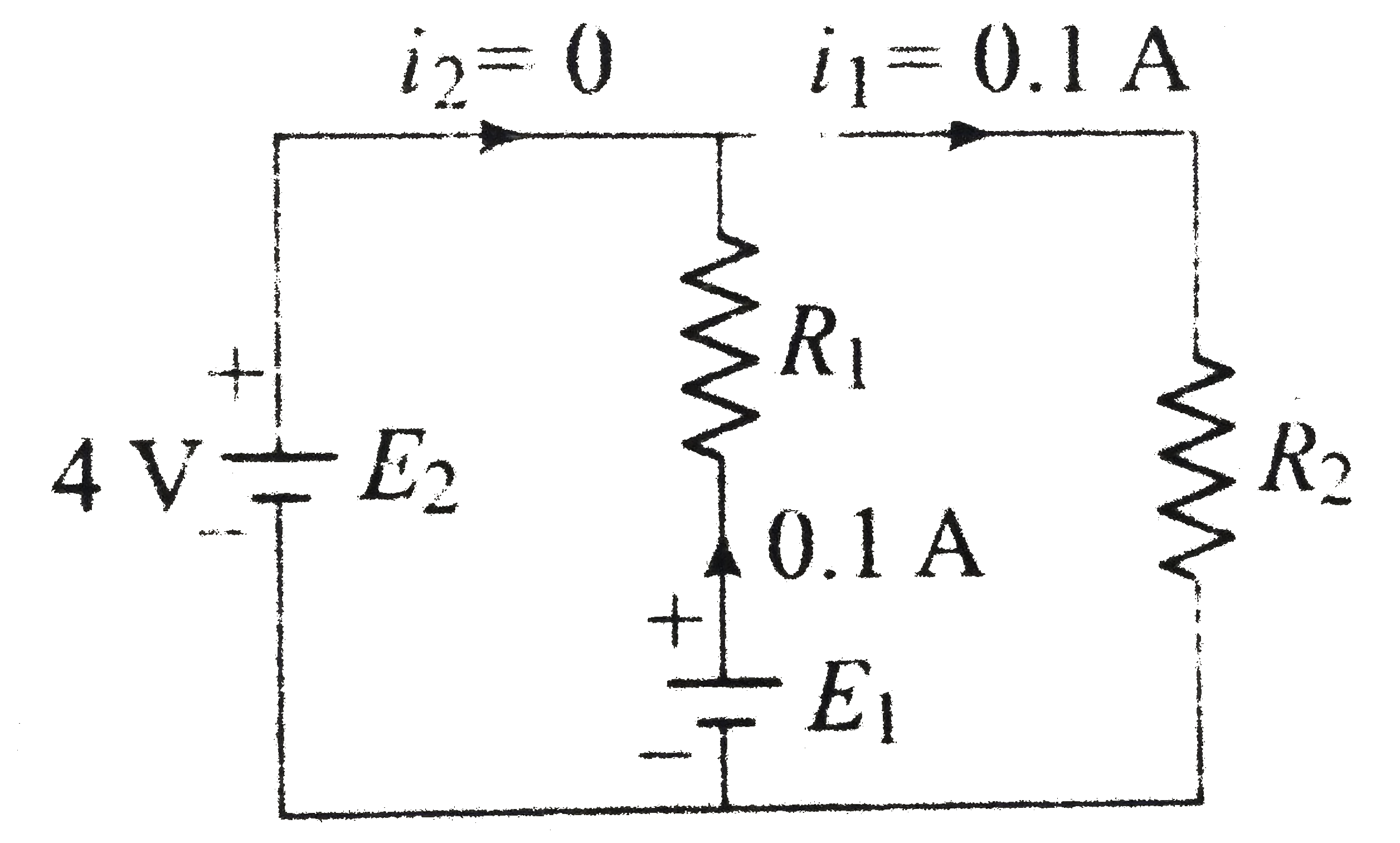 (ii) Now `i_2 = 0.3A, i_1 = 0.1 A, E_2 = 8A`. Now `0.1R_1 + E_1 - 8 =0 ` `0.1 + 4 -E_1 = 0` `0.2 R_1 - 4 = 0` or `R_1 = 4/0.2 = 20 Omega` `0.2 E_1 = 2+4 = 6V`. 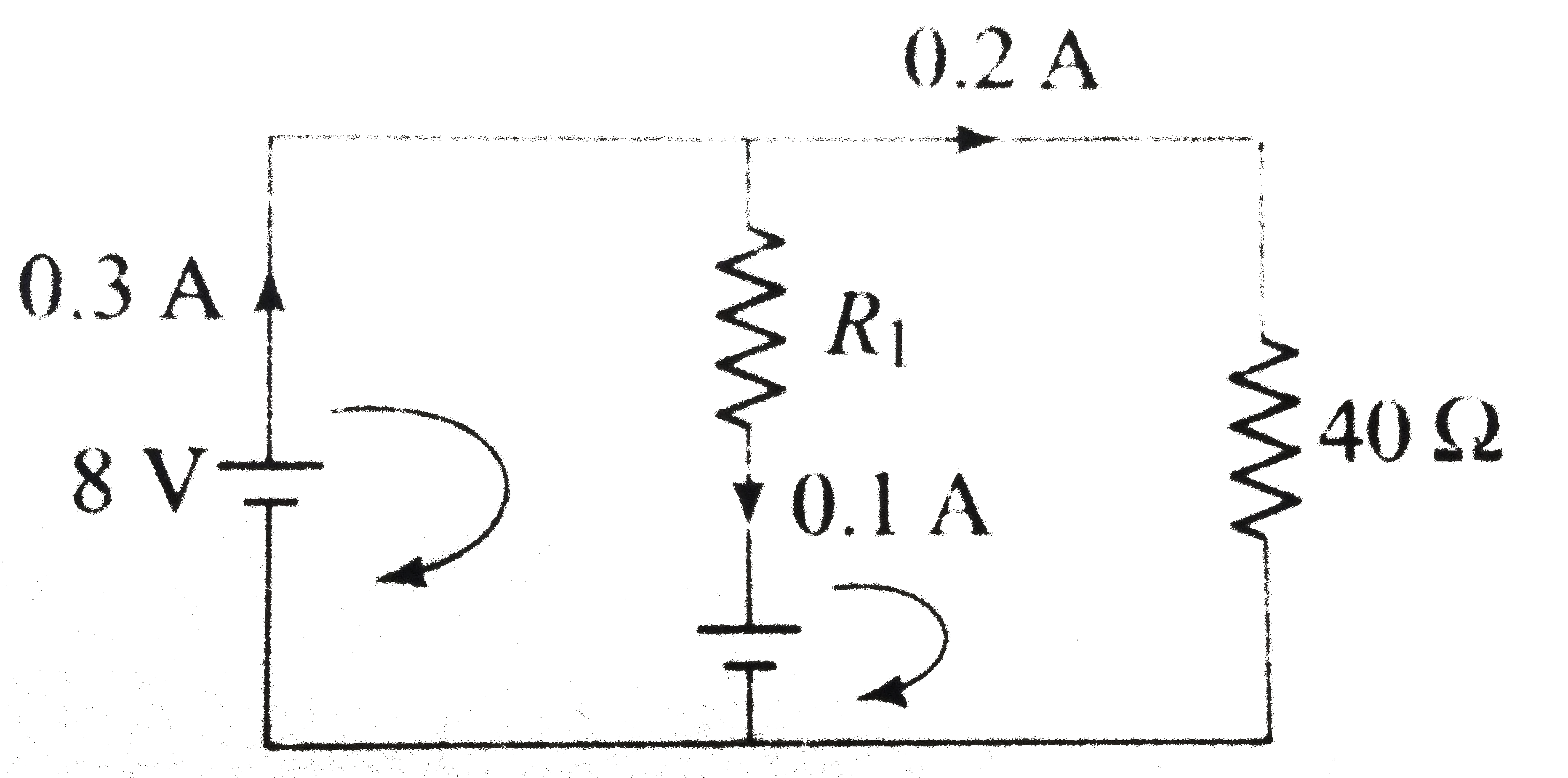
|
|