Saved Bookmarks
| 1. |
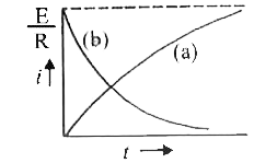
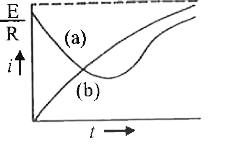
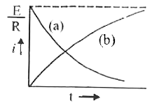
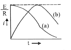
In the circuits (A) and (b) switches S_(1) and S_(2) are closed at t = 0 and are kept closed for a long time.The variation of current in the two circuits for t ge 0 are roughly shown by figure (figures are schematic and not drawn to scale): |
|
Answer»
For inductor circuit, `i = i_(0)(1 - e^(-(Rt)/(L)))` Hence graph (c) CORRECTLY DEPICTS i versus t graph. |
|